


Описание RS232 на примере шлюза Teltonika TRB142
ООО «Цифровой Ангел»
Функция RS232 предназначена для использования последовательного интерфейса устройства. Последовательные интерфейсы предоставляют устаревшим устройствам возможность доступа к IP-сетям. Эта глава является обзором раздела RS232.
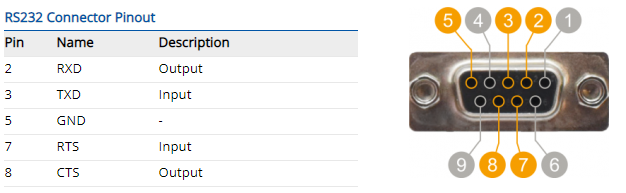
Распиновка разъема RS232
Тип разъема RS232 на этом устройстве - гнездо DCE. DCE обозначает оборудование для передачи данных.
Кабели
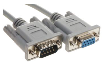
Существует два типа последовательных устройств RS232: DTE и DCE. DTE обычно относится к последовательному порту на ПК или терминале, а DCE относится к устройствам связи. Разъемы, установленные на DTE, скорее всего, будут штекерными, а разъемы, установленные на DCE, - скорее всего, штекерными.
Это устройство DCE и имеет гнездовой разъем.
Для подключения стандартного устройства DTE используйте прямой кабель «мама / папа» RS232:
Смотрите прямую распиновку кабеля ниже:
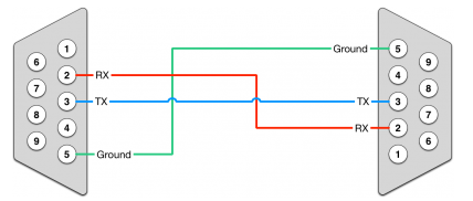
Для подключения другого устройства DCE к RUT955 необходимо использовать нуль-модемный (перекрестный) папа/ папа кабель:
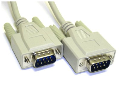
См. Прямую распиновку распиновки кабеля ниже:
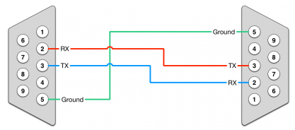
Максимальная длина кабеля составляет 15 метров или длина кабеля равна емкости 2500 пФ (для скорости передачи 19200 бод). Использование кабелей с меньшей емкостью может увеличить расстояние. Уменьшение скорости связи также может увеличить максимальную длину кабеля.
Конфигурация RS232
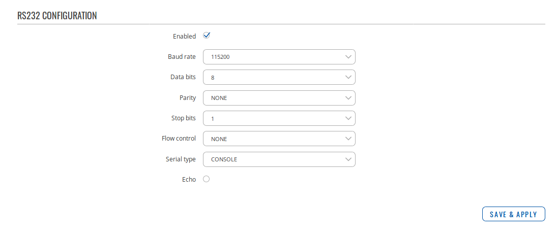
Раздел Конфигурация RS232 используется для настройки параметров последовательного соединения RS232. Используемые параметры следует выбирать в соответствии с потребностями пользователя и типом устройства, подключенного через порт RS232.
На рисунке ниже приведен пример раздела конфигурации RS232, а в таблице ниже приведена информация о полях, содержащихся в этом разделе:
| Имя | Значение | Описание |
|---|---|---|
| Enabled | yes | no; Default: no | Enables the RS232 service |
| Baud rate | 300 | 1200 | 2400 | 4800 | 9600 | 19200 | 38400 | 57600 | 115200; Default: 115200 | Data rate for serial data transmission (in bits per second) |
| Data bits | 5 | 6 | 7 | 8; Default: 8 | Number of data bits for each character |
| Parity | None | Odd | Even; Default: None |
In serial transmission, parity is a method of detecting errors. An extra data bit is sent with each data character, arranged so that the number of 1 bits in each character, including the parity bit, is always odd or always even. If a byte is received with the wrong number of 1s, then it must have been corrupted. However, an even number of errors can pass the parity check.
|
| Stop bits | 1 | 2; Default: 1 | Stop bits sent at the end of every character allow the receiving signal hardware to detect the end of a character and to resynchronise with the character stream. Electronic devices usually use one stop bit. Two stop bits are required if slow electromechanical devices are used |
| Flow control | None | RTS/CTS | Xon/Xoff; Default: None |
In many circumstances a transmitter might be able to send data faster than the receiver is able to process it. To cope with this, serial lines often incorporate a "handshaking" method, usually distinguished between hardware and software handshaking.
|
| Serial type | Console | Over IP | Modem | Modbus gateway | NTRIP client; Default: Console | Serial connection type. More information on each serial type can be seen below or by clicking on a link in the value section |
| Echo | yes | no; Default: no |
Toggles RS232 echo ON or OFF. RS232 echo is a loopback test usually used to check whether the RS232 cable is working properly
|
Серийные типы
Последовательное соединение RS232 может работать по-разному в зависимости от потребностей пользователя и того, какие устройства подключены к порту RS232. Этот раздел главы представляет собой обзор всех различных серийных типов RS232.
Консоль
В режиме консоли последовательный интерфейс настраивается как консоль Linux, которую можно использовать для управления устройством (подобно обычному соединению SSH, за исключением того, что устанавливается через RS232). Его можно использовать для целей отладки, для получения статуса устройства или для управления им. Нажмите здесь, чтобы найти руководство по настройке RS232 в режиме консоли.
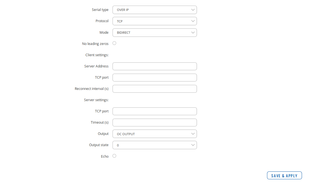
По IP
В последовательном типе Over IP устройство обеспечивает подключение к сети TCP / IP для устройств, подключенных через последовательный интерфейс. На рисунке ниже приведен пример доступных полей конфигурации для последовательного типа Over IP, а в таблице ниже приведена информация об этих полях:
| Имя | Значение | Описание |
|---|---|---|
| Protocol | TCP; Default: TCP | Protocol used in the communication process |
| Mode | Server | Client | Bidirect; Default: Server |
Device's role in the connection:
|
| No leading zeros | yes | no; Default: no | When checked, indicates that the first hex zeros should be skipped |
| Client settings: Server address | ip | host; Default: none | IP address or hostname of the server that the client will connect to |
| Client settings: TCP port | integer [0..65535]; Default: none | Server's port number |
| Client settings: Reconnect interval (s) | integer; Default: none | Time period (in seconds) between reconnection attempts in case a connection fails |
| Server settings: TCP port | integer [0..65535]; Default: none | Internal TCP port number used to listen for incoming connections |
| Server settings: Timeout (s) | integer; Default: none | Disconnects clients after they remain inactive for an amount time (in seconds) specified in this field |
| Output | OC Output | Relay Output; Default: OC Output | Output to indicate that the application switched from client (default) to server state (this field becomes visible only in Bidirect mode) |
| Output state | 1 | 0; Default: 0 | Output state value during which the application reverts to server mode (this field becomes visible only in Bidirect mode) |
Модем
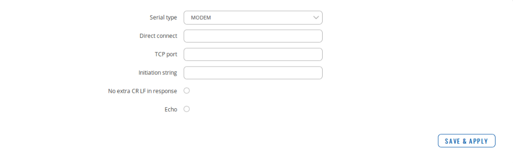
В последовательном типе модема устройство имитирует модем коммутируемого доступа. Соединения с сетями TCP / IP могут быть установлены с помощью AT-команд. Соединение может быть инициировано устройством, подключенным через последовательный интерфейс RS232 с помощью команды ATD: ATD <HOST>: <PORT>. Если заданы параметры прямого подключения, подключение к серверу всегда активно. В режим данных можно войти, введя команду ATD. Входящие соединения обозначаются отправкой RING на последовательный интерфейс.
На рисунке ниже приведен пример доступных полей конфигурации для серийного типа модема, а в таблице ниже приведена информация об этих полях:
| Имя | Значение | Описание |
|---|---|---|
| Direct connect | ip:port | host:port; Default: none | Maintains a constant connection to the specified host. Leave empty if you are planning to use an ATD command to initiate the connection |
| TCP port | integer [0..65535]; Default: none | Internal TCP port number used to listen for incoming connections. Leave it empty to disable incoming connections |
| Initiation string* | string; Default: none | A command string that will be sent to the modem to initiate the connection in some particular way (optional) |
| No extra CR LF in response | yes | no; Default: no | Removes extra CR LF before response code; removes LF after response code |
* Это набор команд AT, используемый в режиме модема последовательных интерфейсов:
| Команда | Описание | Использование |
|---|---|---|
| A | Answers an incoming call | To answer incoming connection: ATA |
| D | Dials a number |
To initiate data connection: ATD <HOST>:<PORT> To enter data mode with Direct connect settings: ATD |
| E | Local echo |
Turn local echo ON: ATE1 Turn local echo OFF: ATE0 |
| H | Hang up current call | To end data connection: ATH |
| O | Return to data mode | To return to data mode from command mode: ATO |
| Z | Reset to default configuration |
To reset the modem to default configuration: ATZ
|
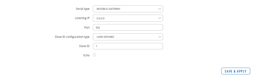
Modbus шлюз
Последовательный тип шлюза Modbus позволяет перенаправлять данные TCP, поступающие на указанный порт, в RTU, указанный в качестве ведомого идентификатора. Идентификатор ведомого может быть указан пользователем или получен непосредственно из заголовка Modbus.
На рисунке ниже приведен пример доступных полей конфигурации для серийного типа шлюза Modbus, а в таблице ниже приведена информация об этих полях:
| Имя | Значение | Описание |
|---|---|---|
| Listening IP | ip; Default: 0.0.0.0 | IP address on which the Modbus gateway will wait for incoming connections |
| Port | integer [0..65535]; Default: 502 | Port number used to listen for incoming connections |
| Slave ID configuration | User defined | Obtained from TCP; Default: User defined | Specifies whether slave IDs should be user defined or automatically obtained from TCP |
| Slave ID/Permitted slave IDs | integer | range of integers | multiple integers; Default: 1/1-247 |
Slave ID or range of permitted slave IDs. The way this field is named and its function depends on the value of the "Slave ID configuration" field.
|
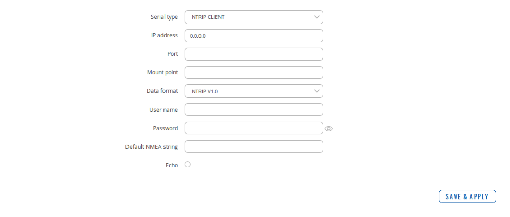
Клиент NTRIP
Сетевой транспорт RTCM через Интернет-протокол (NTRIP) - это протокол для потоковой передачи данных дифференциального GPS (DGPS) через Интернет в соответствии со спецификациями, опубликованными RTCM.
На рисунке ниже приведен пример доступных полей конфигурации для серийного типа клиента NTRIP, а в таблице ниже приведена информация об этих полях:
| Имя | Значение | Описание |
|---|---|---|
| IP address | ip; Default: 0.0.0.0 | IP address of the NTRIP server |
| Port | integer; Default: none | TCP/UDP port used for communication with NTRIP server |
| Mount point | path to a file; Default: none | NTRIP mount point |
| Data format | NTRIP v2.0 TCP/IP | NTRIP v2.0 RSTP/RTP | NTRIP v1.0 | Automatic detection | NTRIP v2.0 UDP; Default: NTRIP v1.0 | NTRIP version |
| User name | string; Default: none | User name used for NTRIP authentication |
| Password | string; Default: none | Password used for NTRIP authentication |
| Default NMEA string | string; Default: none | Optional NMEA string that will be used as the default value when initiating the connection to the NTRIP server (this value is only sent to the server if there is no NMEA from router's GPS device) |
Оборудование
-
 16 884 ₽ руб.Без НДС
Оптовая цена по запросуНадежный шлюз IoT LTE Cat1 с RS232, усовершенствованная микропрограмма на основе Linux с брандмауэром и функциями VPN

На ваш e-mail было отправлено письмо с регистрационной информацией.
Пожалуйста, дождитесь письма, так как контрольная строка изменяется при каждом запросе.